The rear is the assembly instructions for the tail: find the parts shown on the diagram.
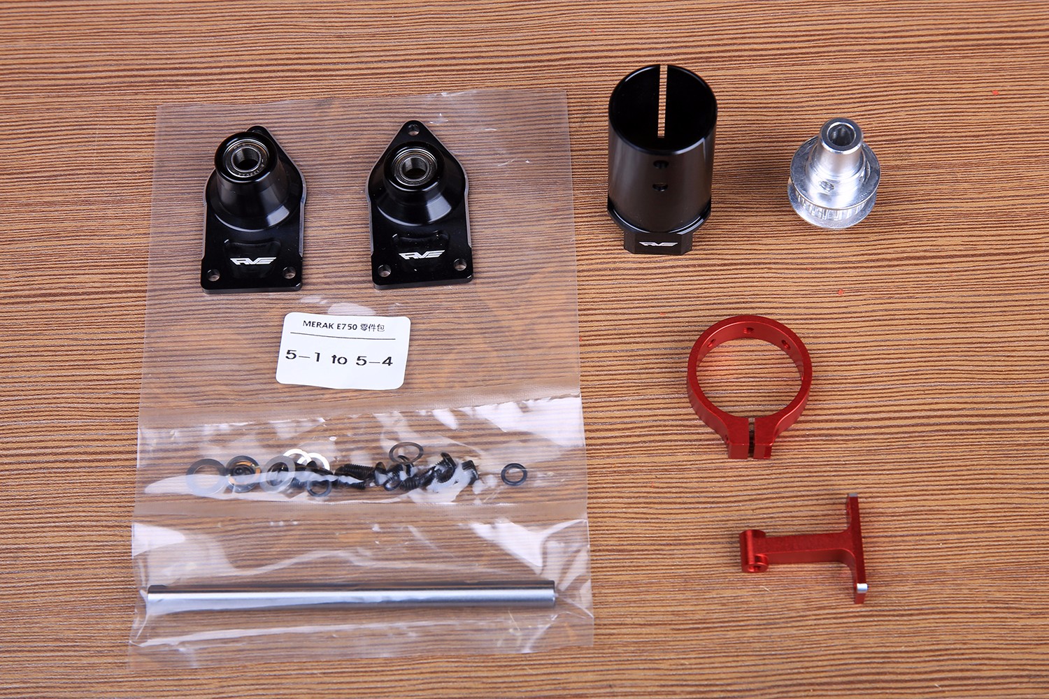
First install the tail box (left) and the tail support column with M3*6 semi-circular head cap screws.
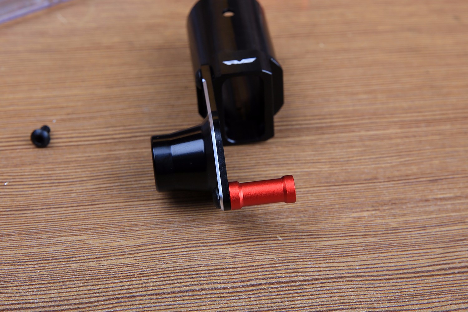
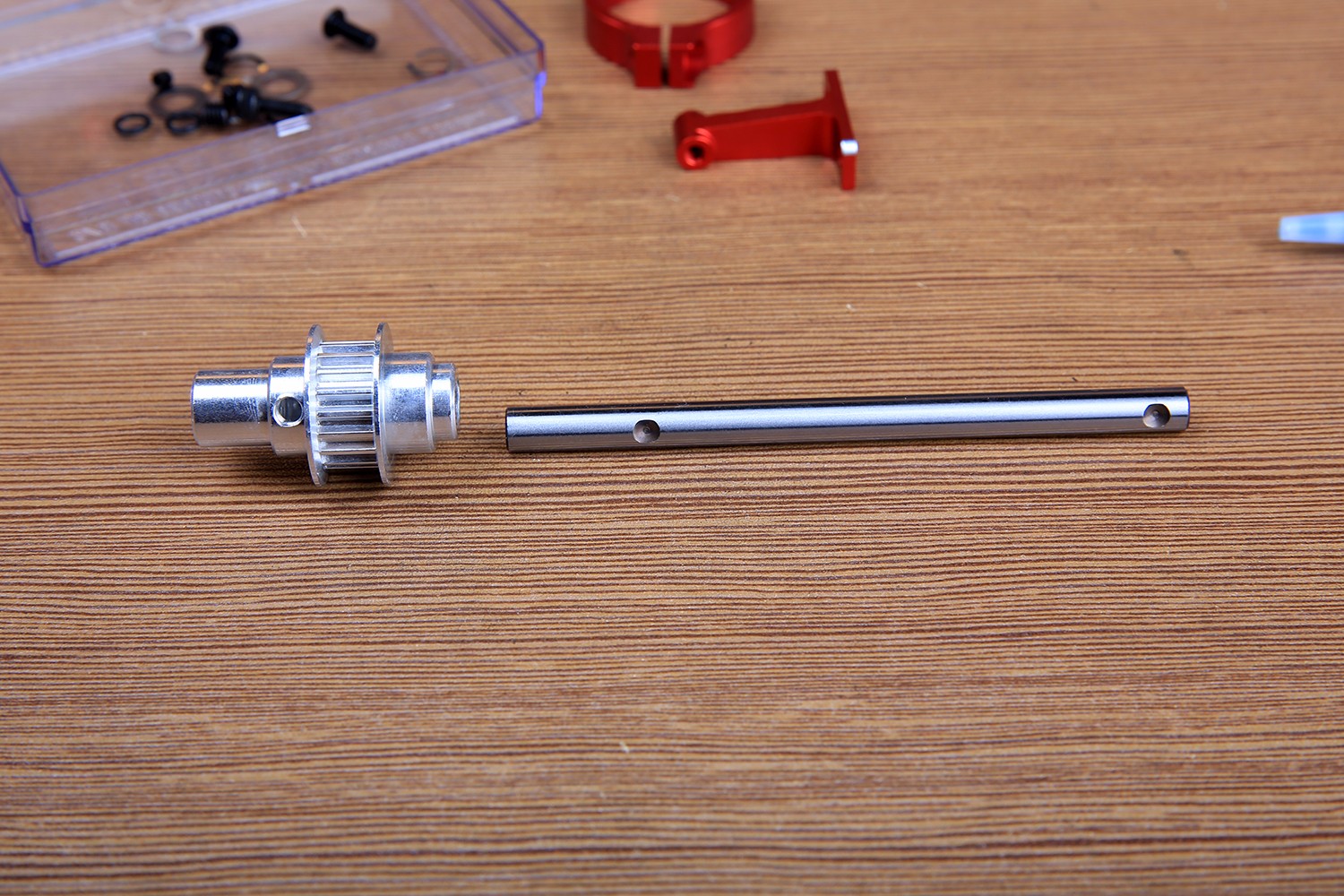
Please pay more attention to the installation direction of the timing pulley.
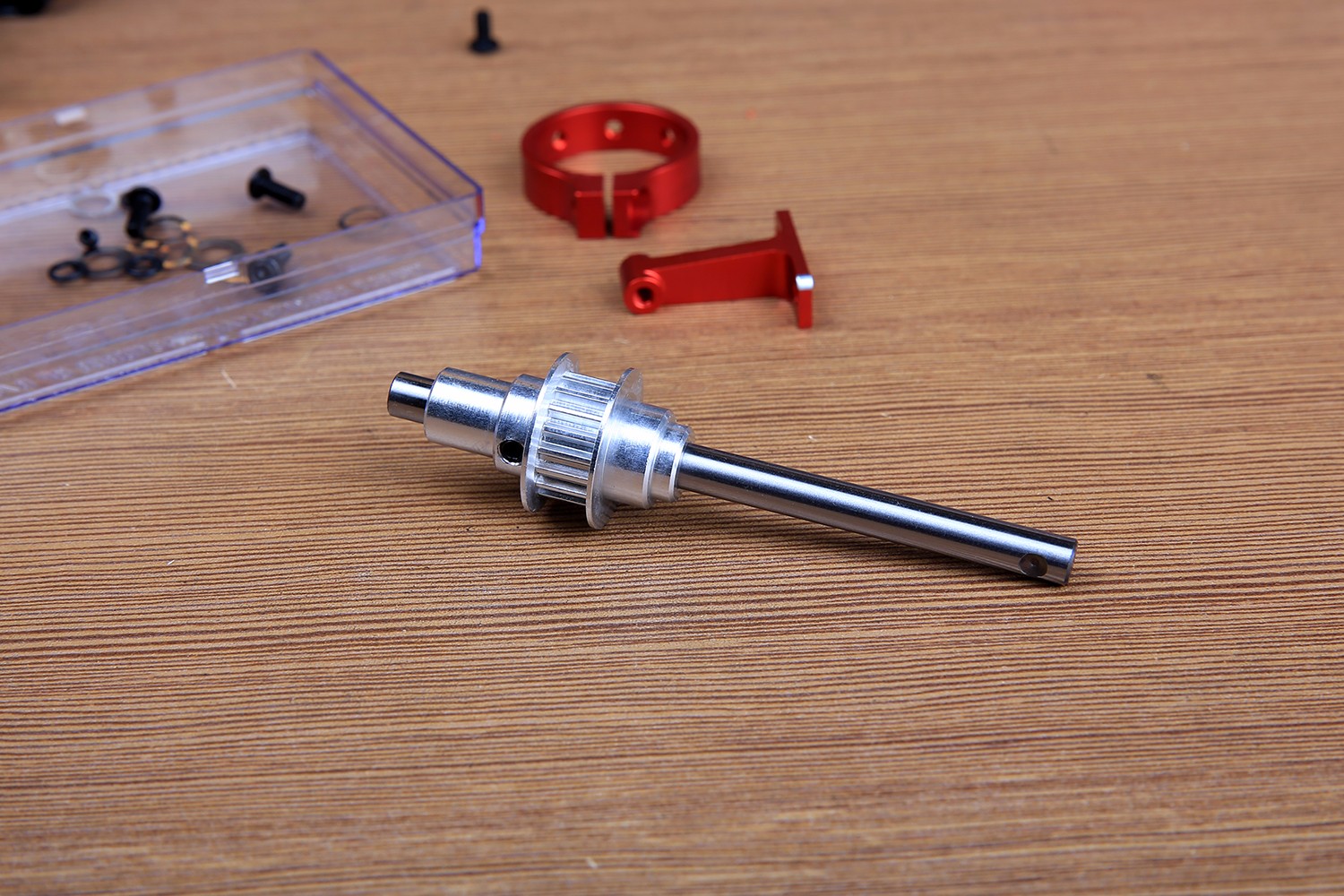
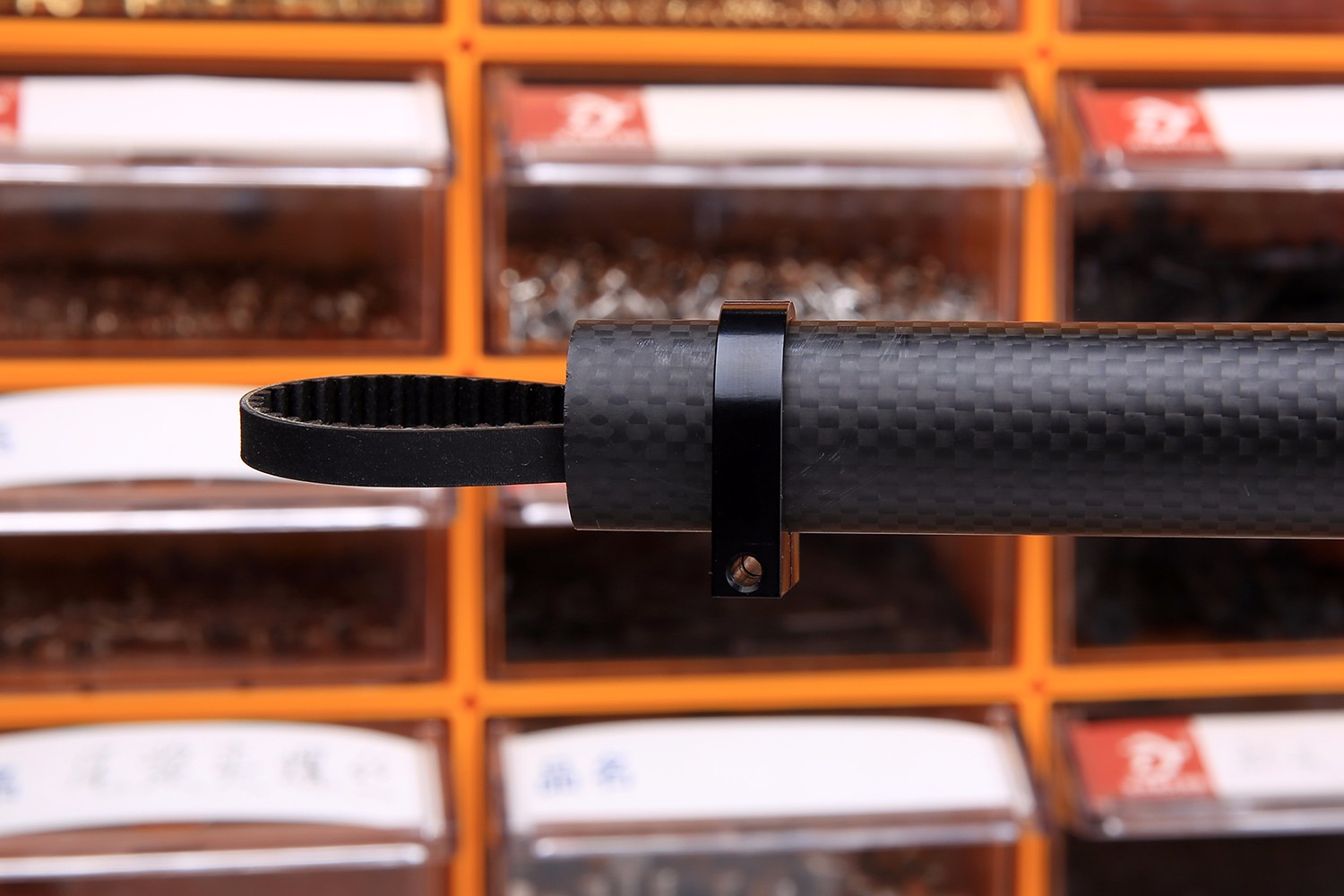
The tail pipe is taken out, and the belt is passed through the pipe and loaded into the tail pipe fixing seat.
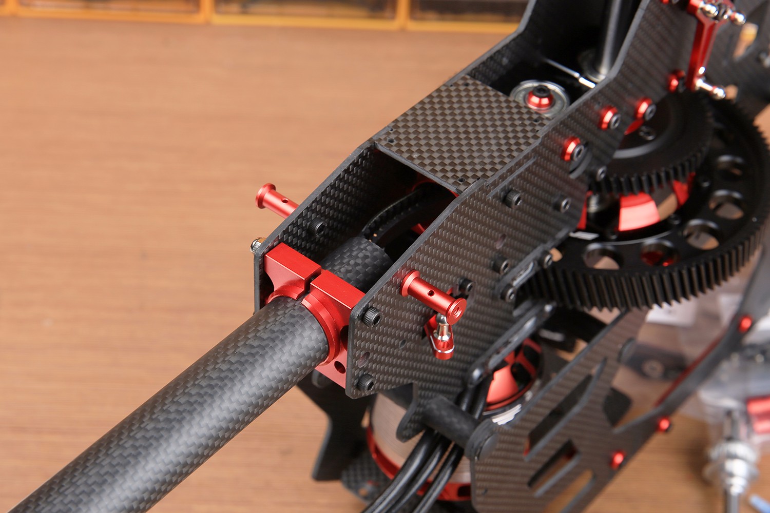
Note that the tail support ring should be inserted into the tail pipe first. If the full cover is installed, it needs to be inserted into the tail shell support sponge.
This red retaining ring is also required to lock the tail box mount, first on the mount and then into the tailpipe.
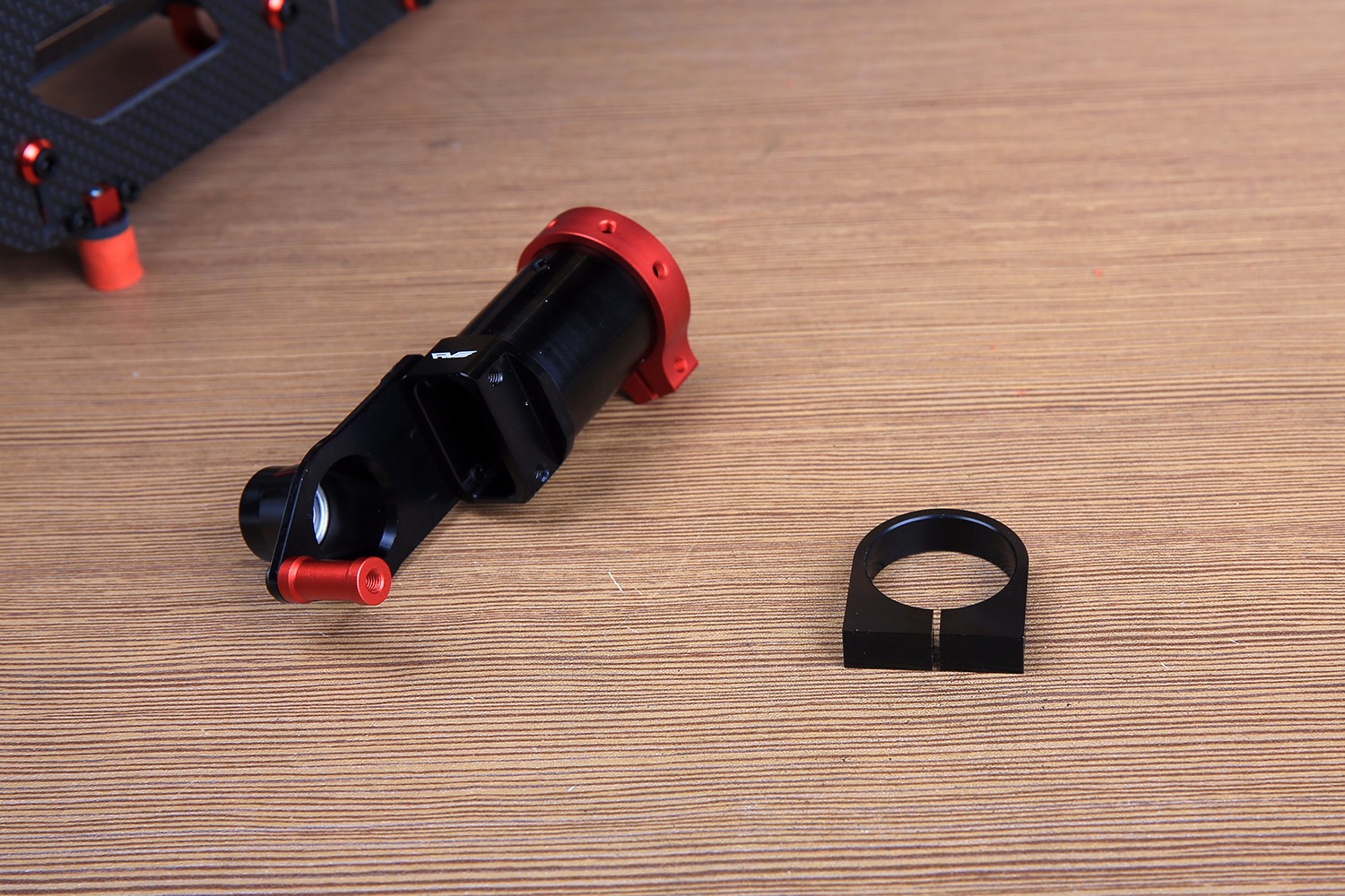
The angle of the fastening ring is as follows. Note that the M3 top wire needs to be slightly pressed after adjusting the angle directly, because it will be directly pressed to the tail pipe, and excessive force locking will cause damage to the tail pipe. This top wire is mainly used to prevent the angle from changing.
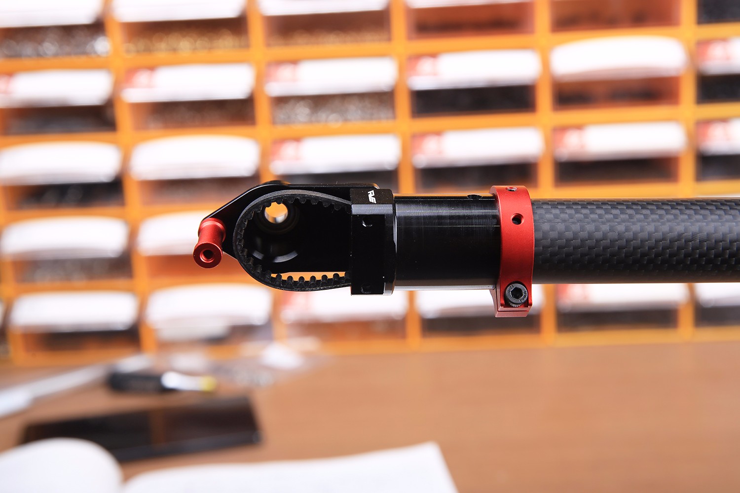
The inside of the belt is inserted into the tail shaft. It should be noted that when the large paddle rotates clockwise, the tail belt should be turned counterclockwise from the angle of the following figure. Please do not install it.
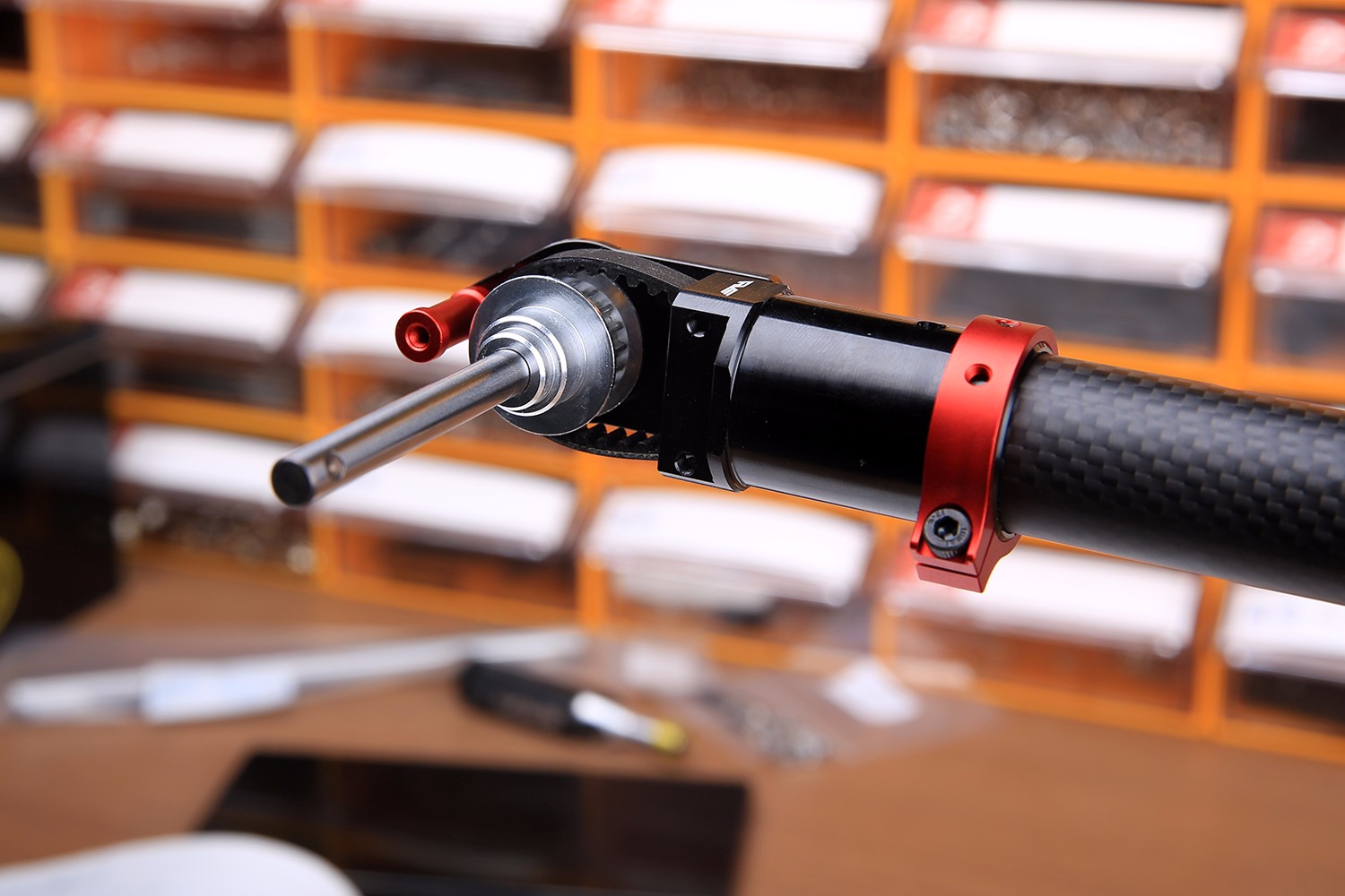
Next, install the right tail box and the tail control arm mount. Pay attention to the side of the mount with two light chamfers facing the head position.The tail sleeve is covered with a rubber ring to the bottom.
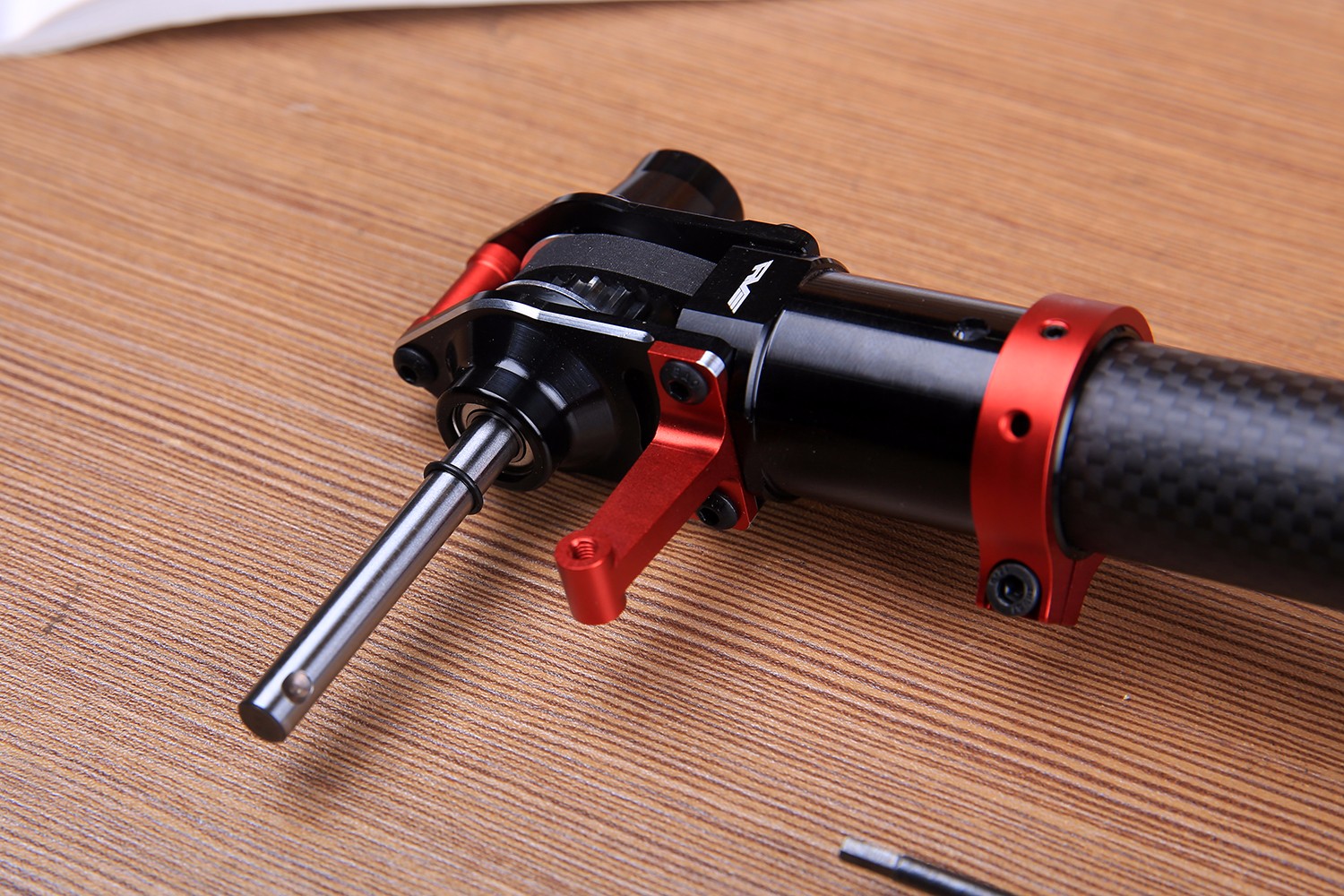
Next is the installation of the tail sleeve assembly:
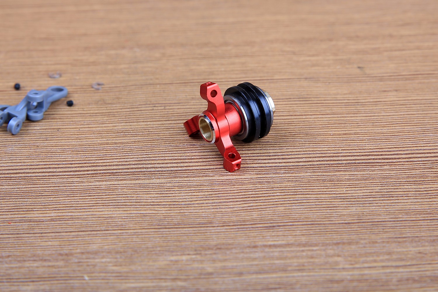
First 5-5 parts and metal parts shown.
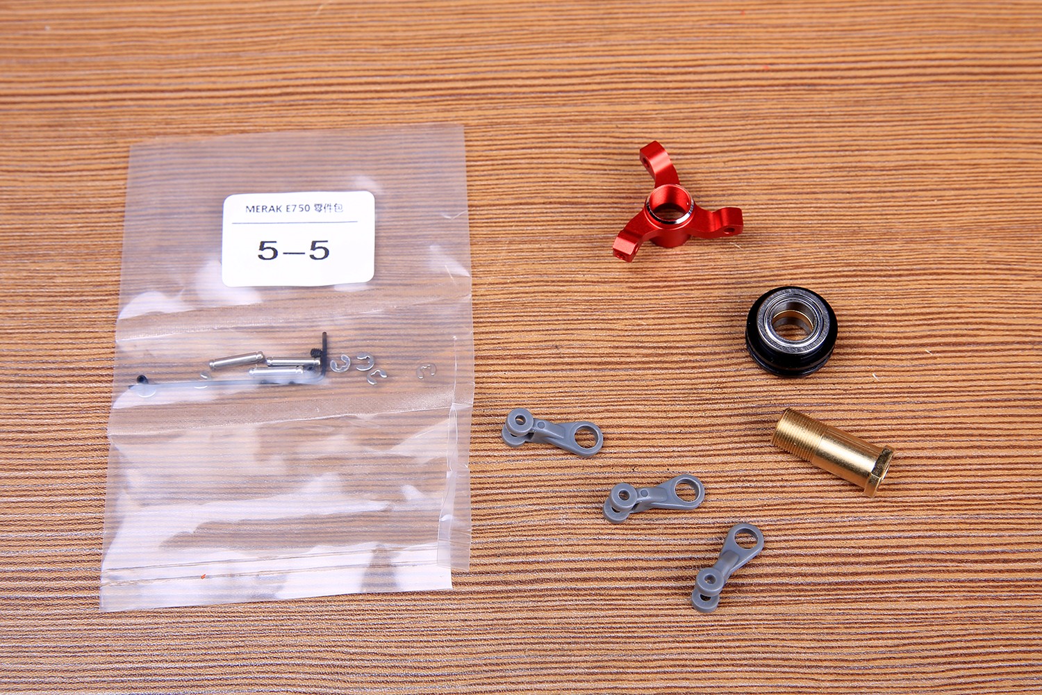
The thread of the copper sleeve and the crab claw is the reverse tooth, please pay attention to the locking direction. Here to explain that this position does not need to be over-tightened, a little blue screw glue and then gently screwed to the bottom, because the anti-thread is relaxed, do not worry about loose, excessive tightening will make the bearing rotation is not smooth.
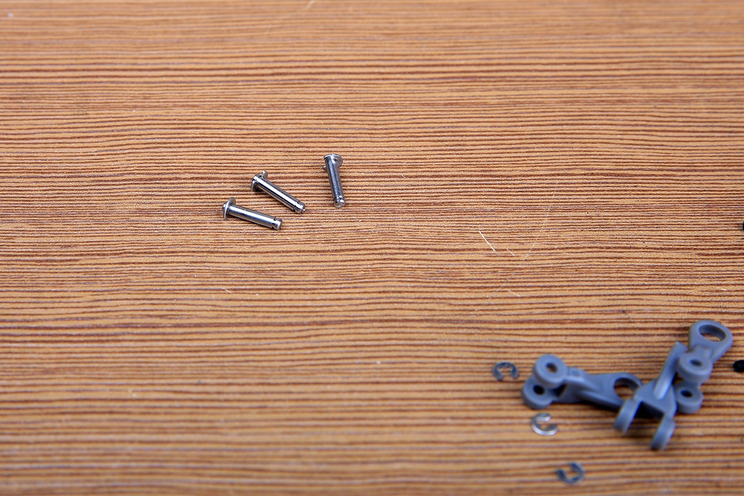
First press the E-type buckle onto the stainless steel shaft with a small needle-nosed pliers.
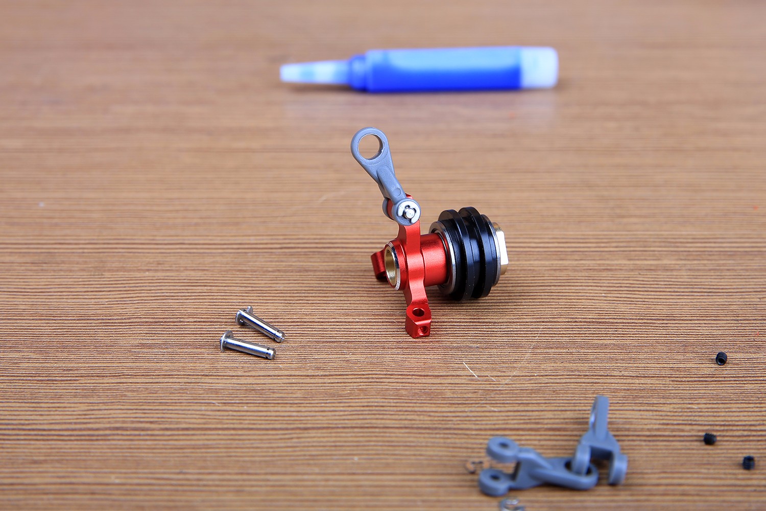
Install the ball buckle and install the buckle on the other side. Pay attention to positive and negative direction of the ball head buckle oh.
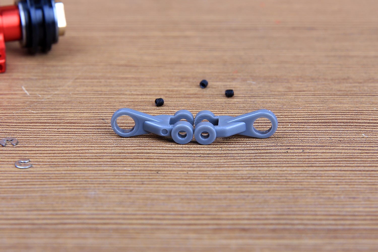
The following figure can compare the positive and negative differences. There is a small dot on the side where the ball enters.
Installed tail slider structure.
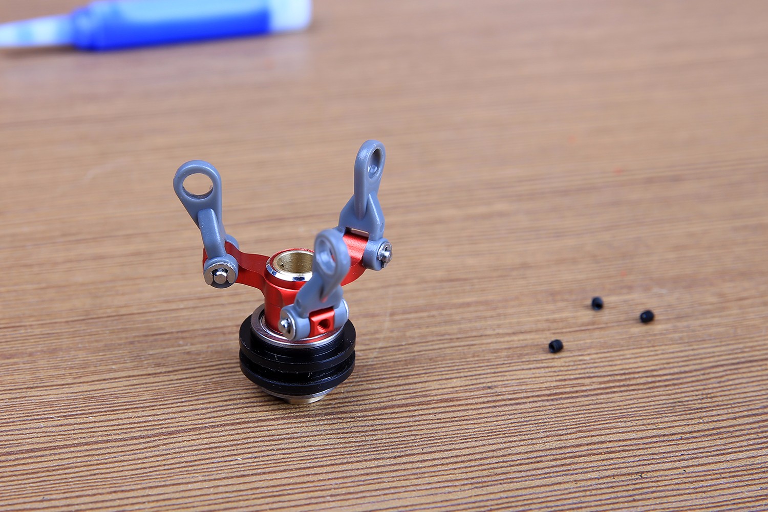
Next is the tail fork, 5-6 parts pack and illustrated parts are ready.
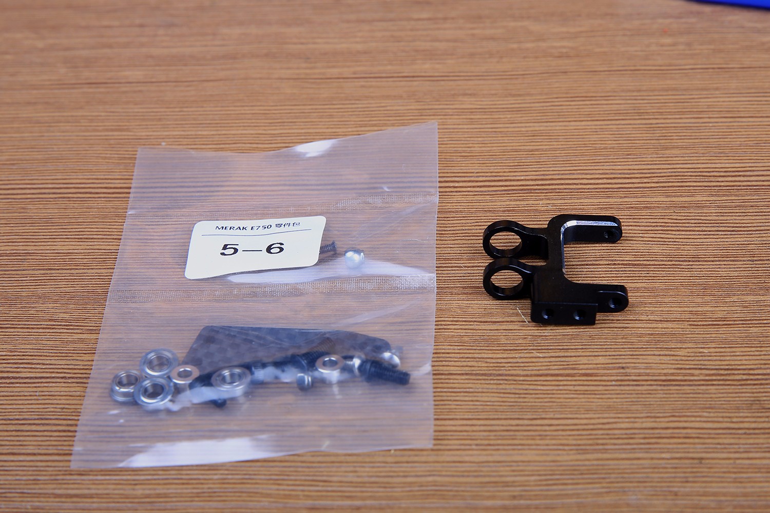
Fix the carbon fiber push-pull arm first.
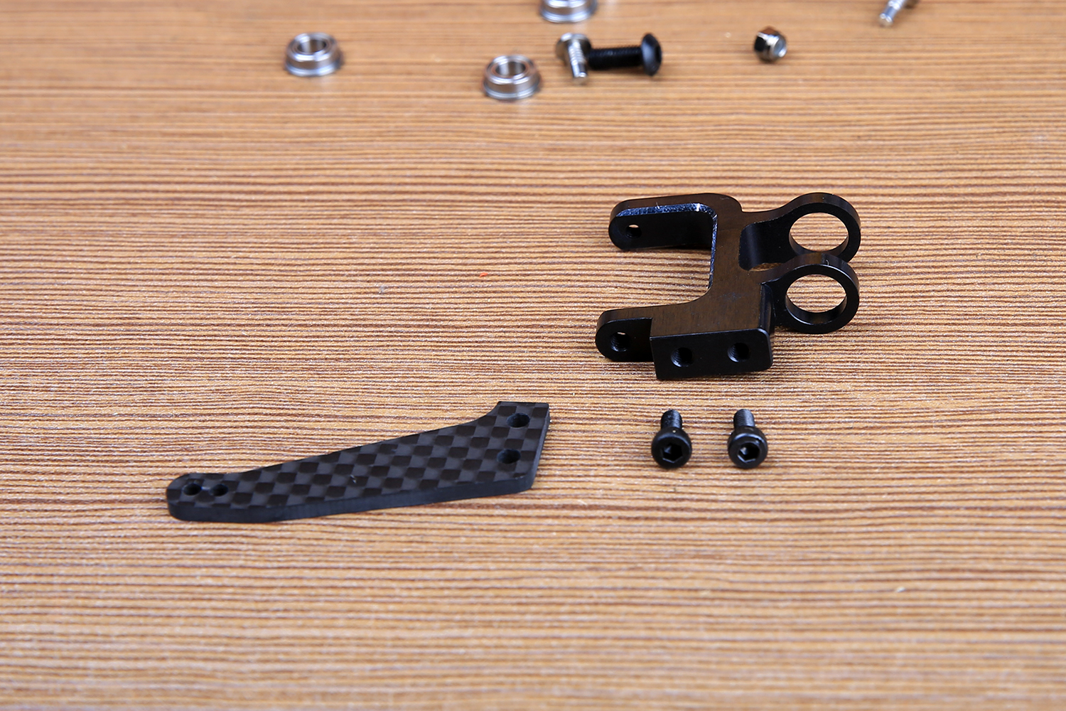
Pay attention to the mounting direction of the push arm.
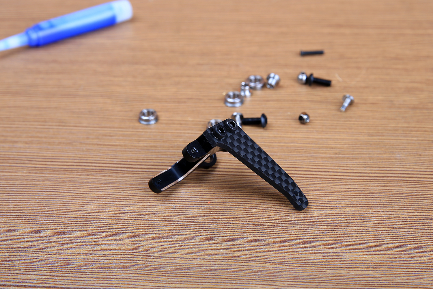
The ball head is mounted in the outermost hole. The fork is made of two special stainless steel screws that are glued and fixed.

Please pay attention to the direction of the ball.
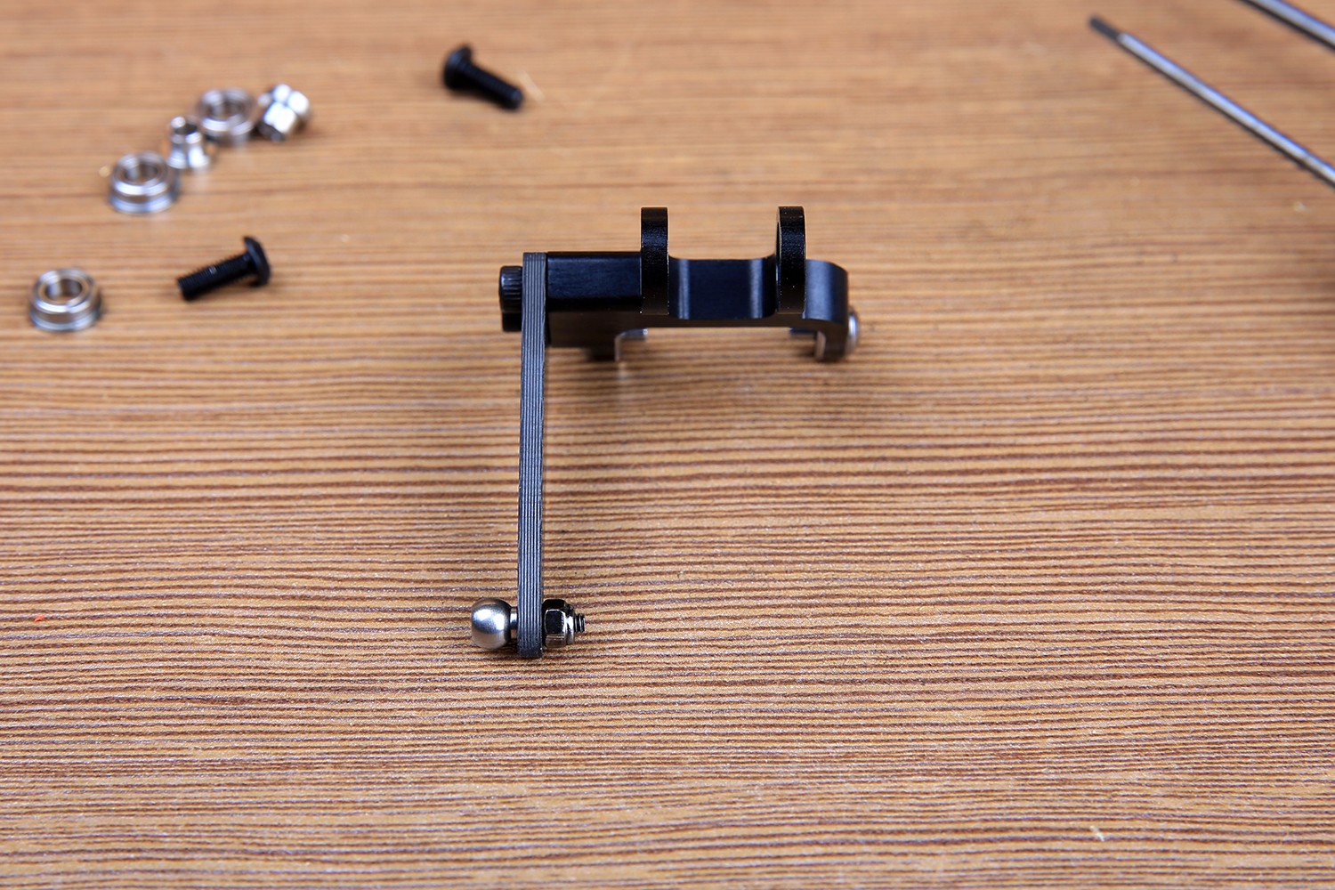
The green rubber on the outer ring of the bearing is pressed into the bearing hole.
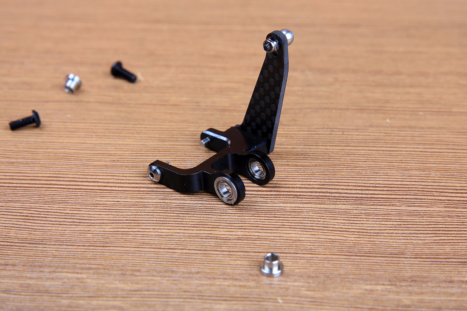
The bearing sleeve is mounted from the inside out.
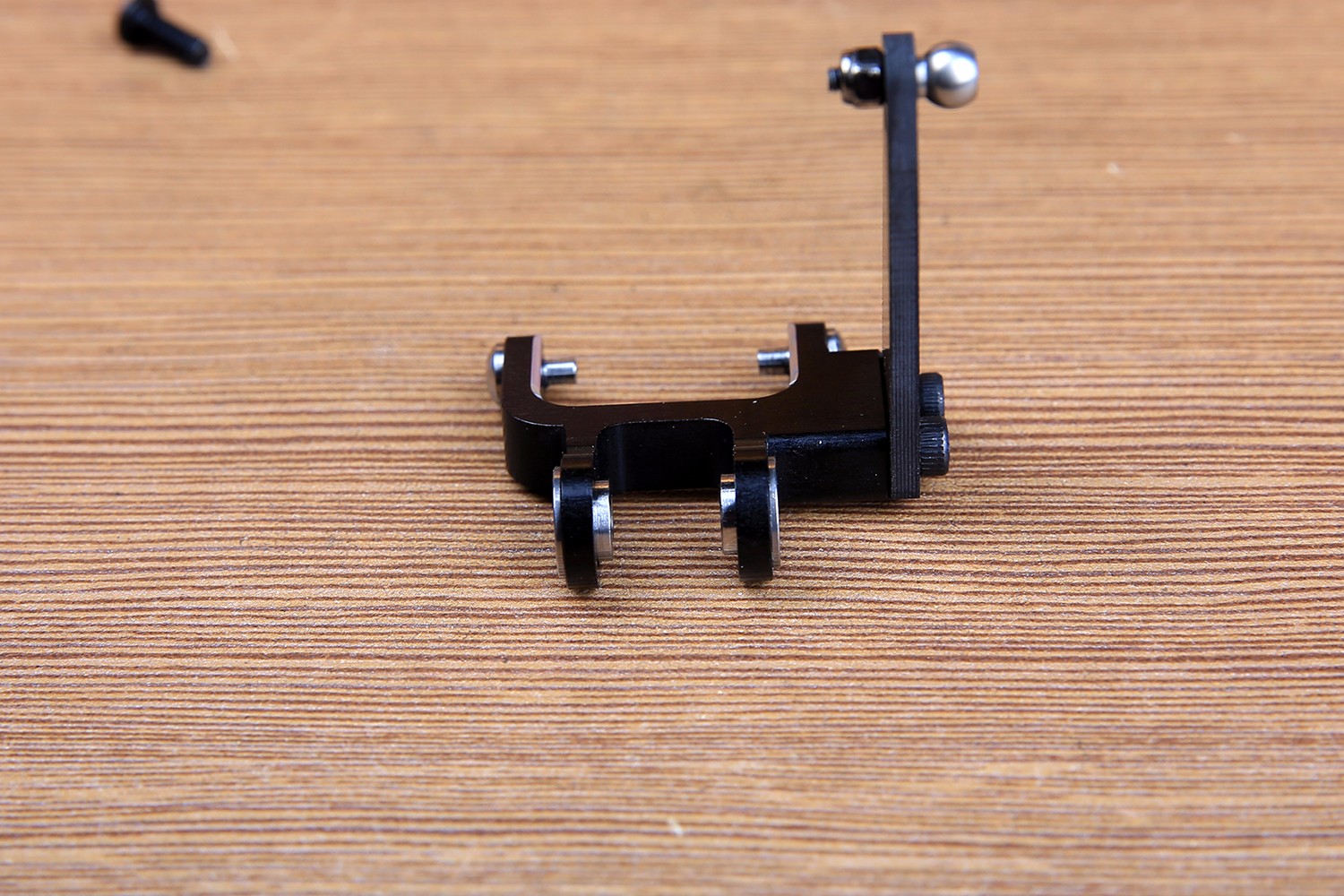
Finally, fix the fork on the mount, paying attention to the carbon fiber push-pull arm facing down.
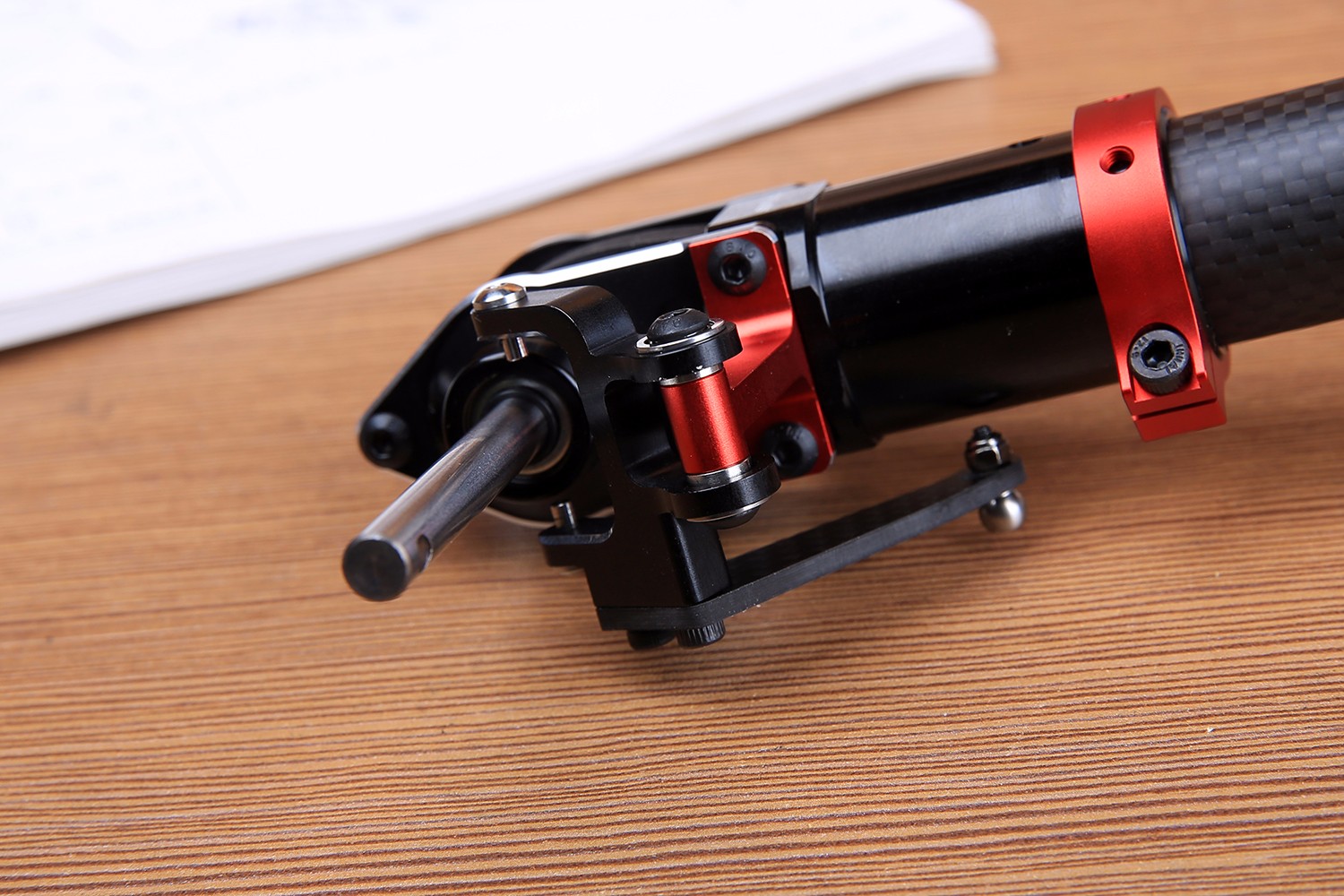
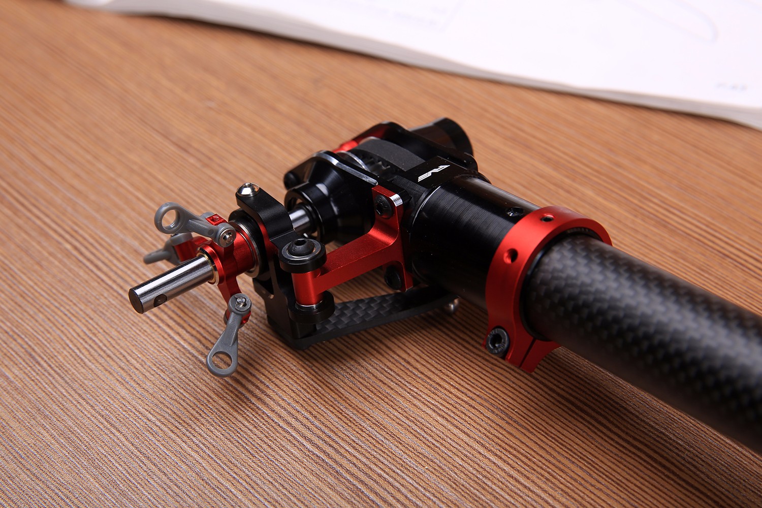
Install the tail slider as well, and note that the fork should be placed in the groove of the slider. This completes the tail-variable structure, and then installs the tail center and tail rotor clamps.
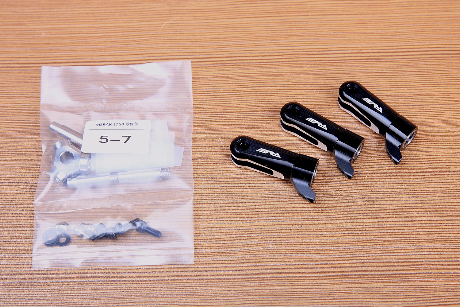
5-7 accessory kit and three tail rotor clips are ready.
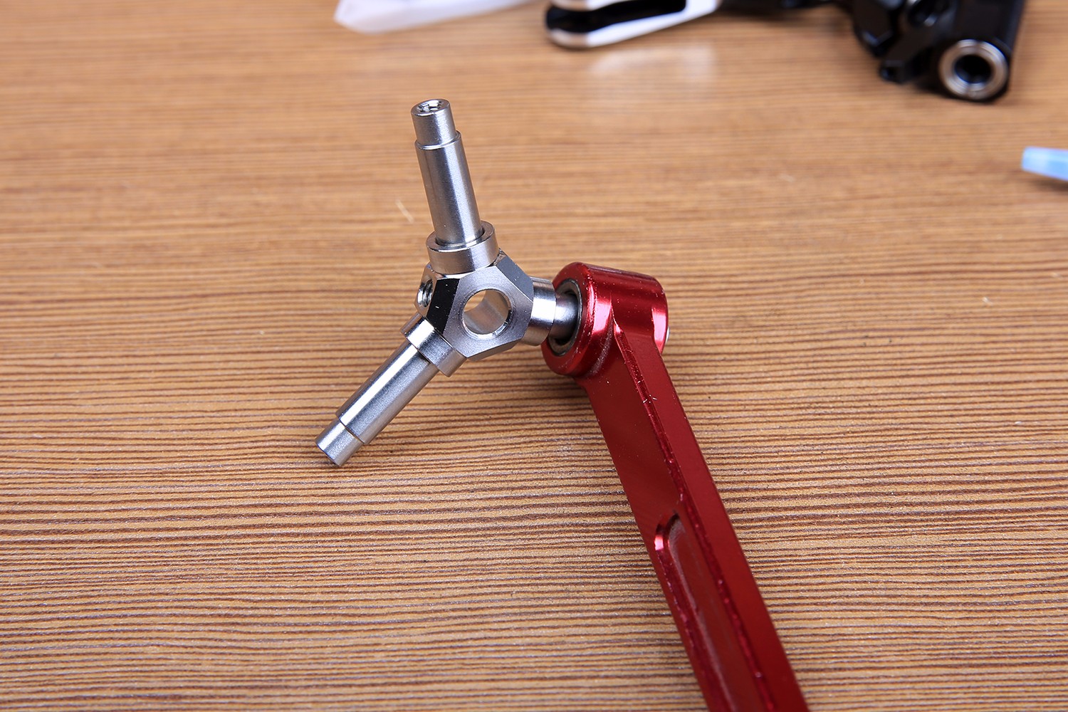
Our tail in the middle is a split structure, first hit the blue screw glue.

Because the tail rotor clamp shaft is 10MM, the 450 horizontal shaft wrench can be used as a disassembly tool for this part.
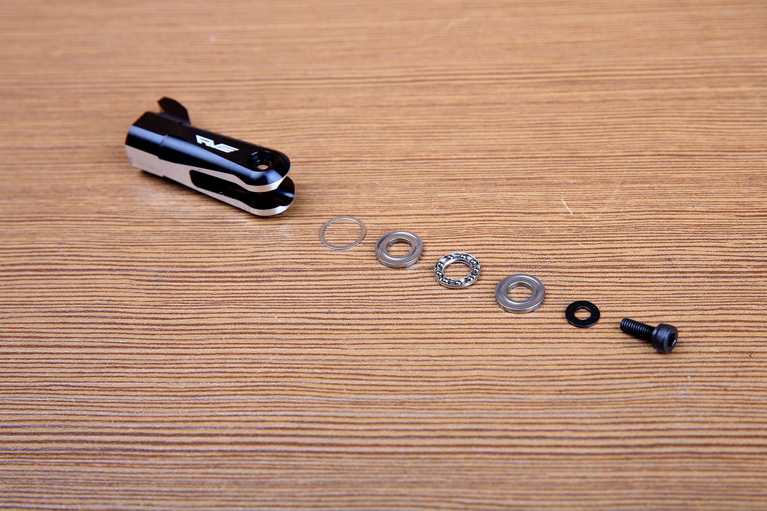
Schematic diagram of the internal bearing structure of the tail rotor clamp:
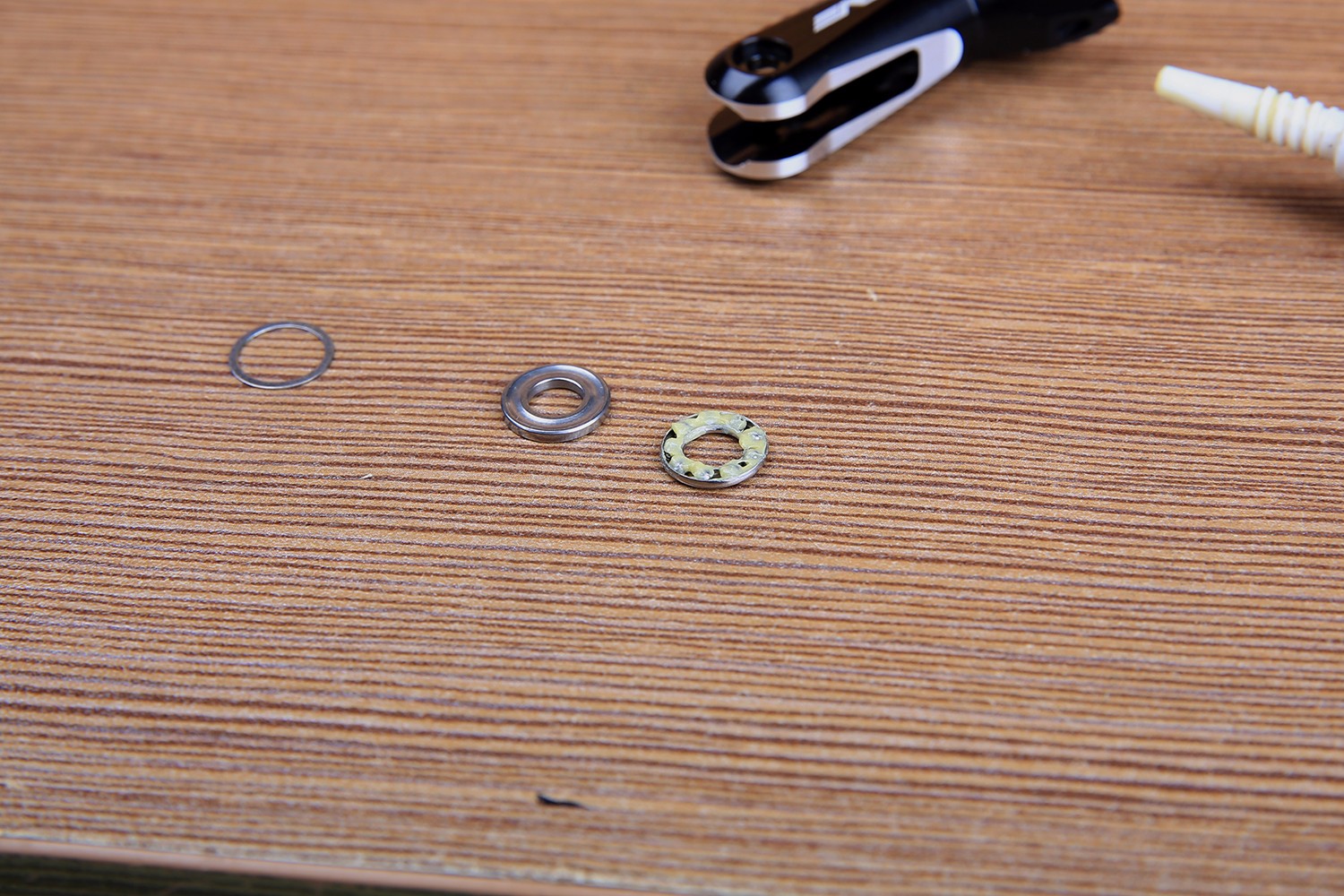
First load a 0.3mm thick gasket, then thrust bearing, M3 gasket, M3 screw. Special attention should be paid to the difference in the size of the inner holes on both sides of the thrust bearing, first placed on the larger side of the inner hole! Be careful! ! !
The thrust bearing ball should be filled with bearing oil.
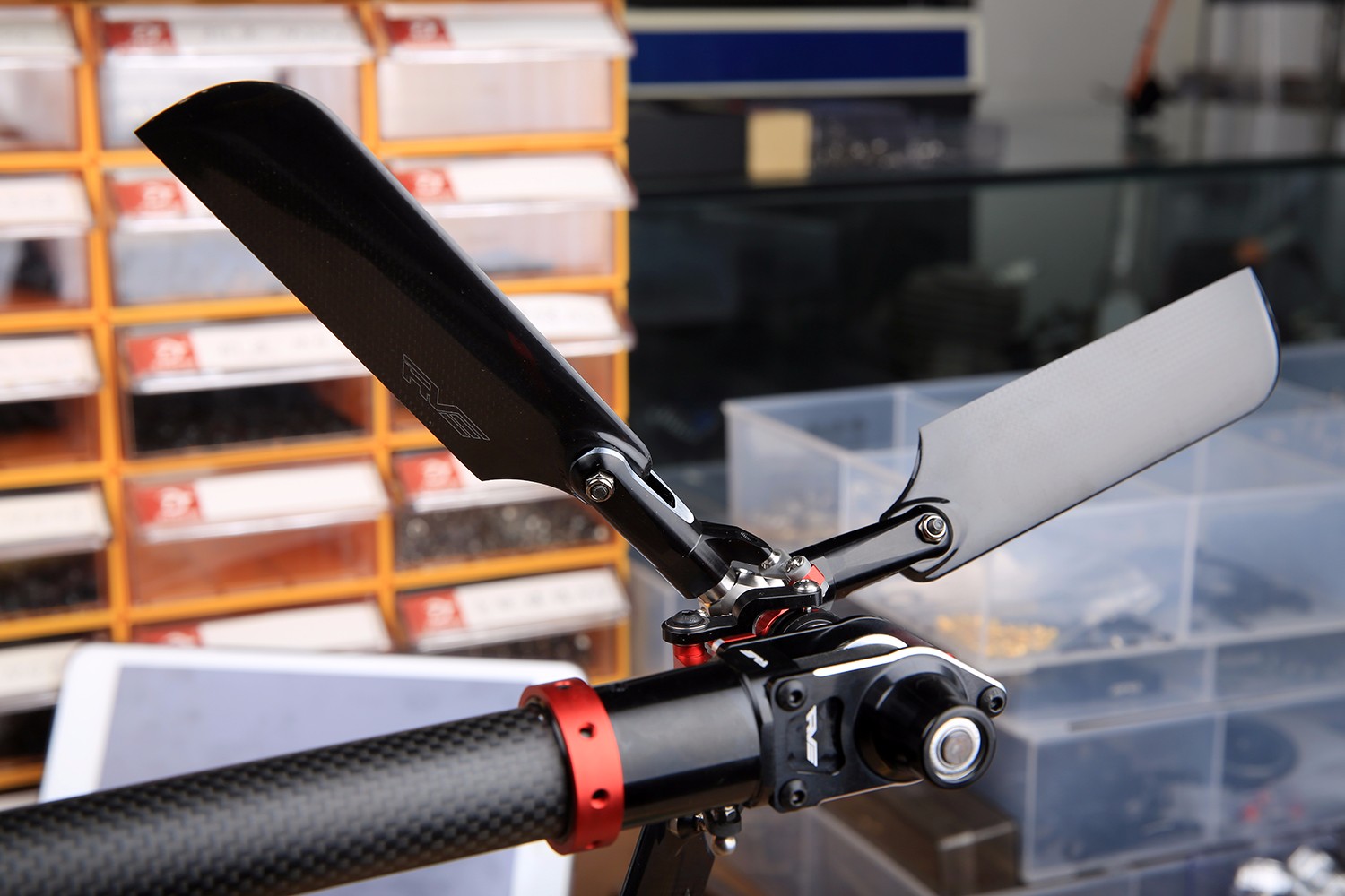
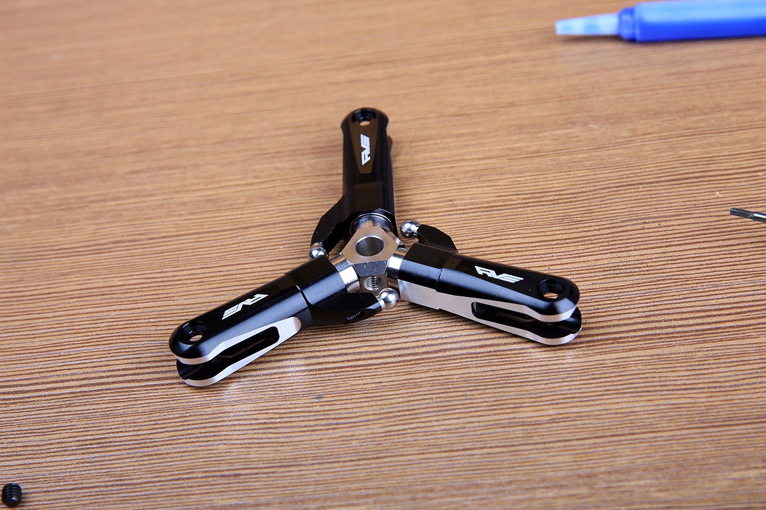
The paddle ball head is made of blue screw glue. Remember not to tighten the ball head too much to avoid the ball head breaking. After the tail three-blade structure is installed, it is attached to the tail shaft and fixed with the M4 top wire. The ball head on the slider is fastened to the paddle ball head.
After the tail structure is installed, first confirm that the tail pipe has been inserted into the bottom of the tail box fixing seat, and then tighten the fastening ring. At this time, it is also necessary to adjust the angle of the belt tension and the tail box. The tail box angle can be adjusted by means of the electronic pitch gauge, first making a reference 0 degree on the plane of the body.
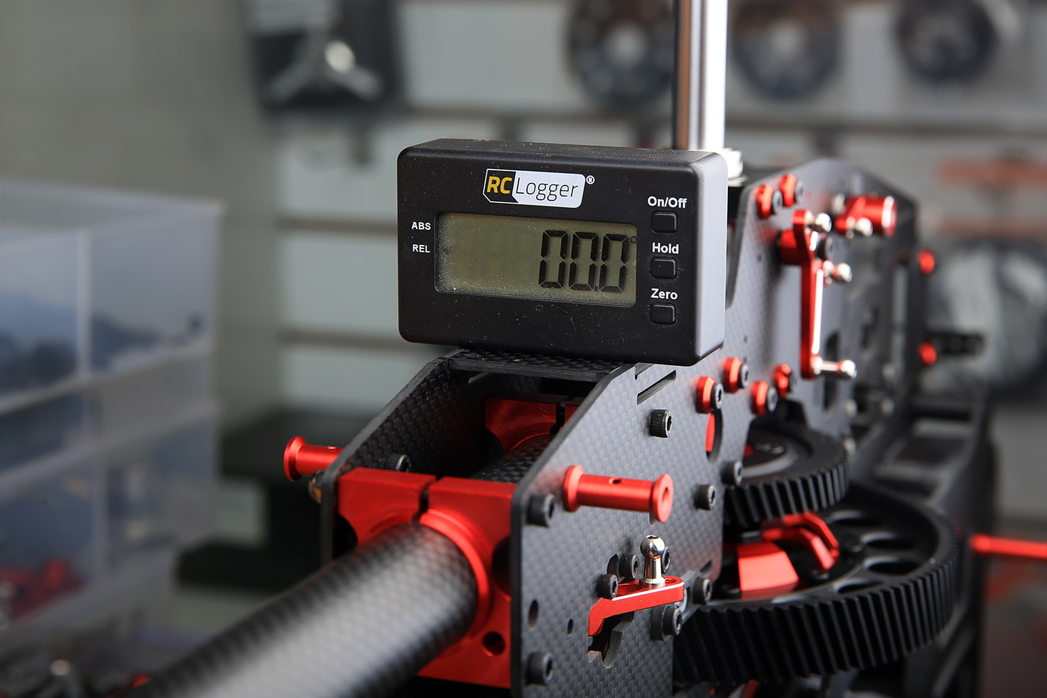
Then place it on the plane of the tailbox and rotate the tailpipe to adjust to 0 degrees.The tightness of the belt is also exquisite, too loose and easy to jump, too tight will lose power, accelerate the belt and pulley and bearing wear. The tightness is generally used to pinch the belt up and down with two fingers from the tail box, and the belt is slightly squeezed without touching it.
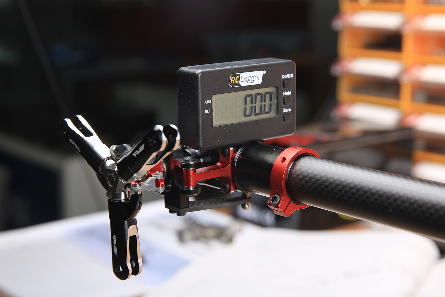
The standard three-tailed paddle length is 105. It has been accurately matched before leaving the factory.
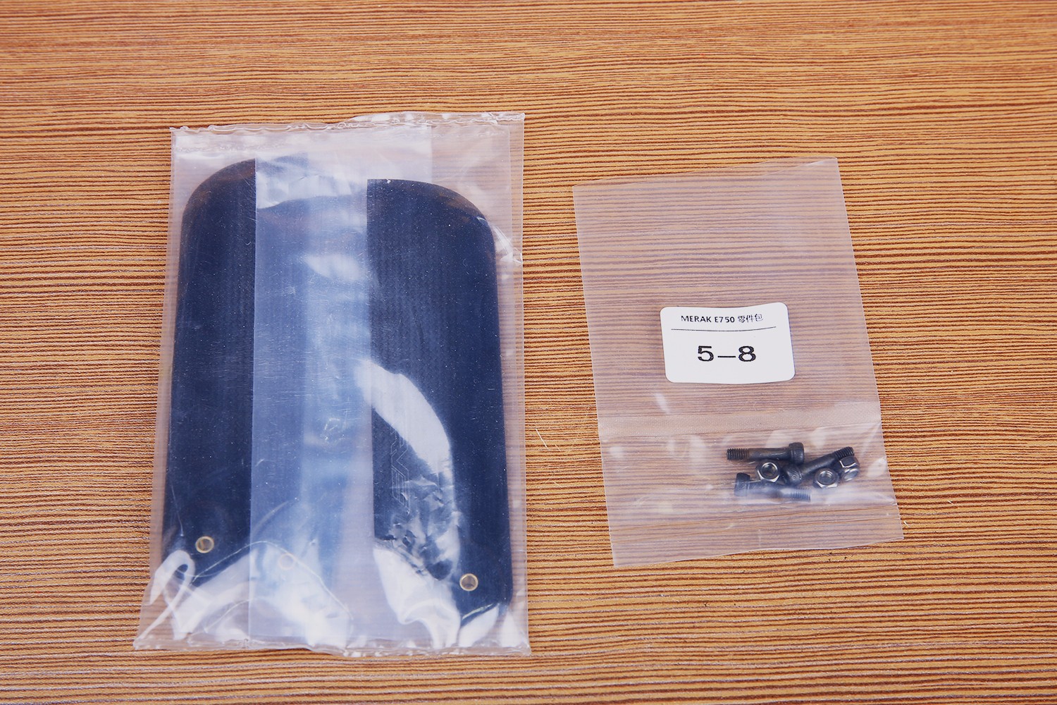
Please pay attention to the direction of the tail rotor installation.
